Difference between revisions of "JEOL 7500F HRSEM"
(→Sample Holders: reworded beginning to include modularity notes) |
(troubleshooting info into table) |
||
| Line 62: | Line 62: | ||
| [[File:TED.png|150px]] || [[File:TEDpic.jpg|150px]] Available upon request | | [[File:TED.png|150px]] || [[File:TEDpic.jpg|150px]] Available upon request | ||
|} | |} | ||
| + | |||
| + | == Troubleshooting Tips == | ||
| + | ''See the SEM Troubleshooting section for more detailed information.'' | ||
| + | |||
| + | To improve image quality, you may need to change one or multiple settings. | ||
| + | {| class = "wikitable" | ||
| + | |+ Troubleshooting Settings | ||
| + | |- | ||
| + | ! Setting !! Range !! Notes | ||
| + | |- | ||
| + | | Scan Speed || 1-12 (arbitrary) || Assignable to 4 presets (quick 1,2 and fine 1,2) Slow speeds (higher numbers) yield less noisy images, but may introduce more charging. Change in Setup > Operation Settings. | ||
| + | |- | ||
| + | | Detector || SEI or LEI (lower) || Both are electron detectors. SEI is positioned directly above the specimen and yields fewer shadows, more material contrast. Best for very flat specimens. SEI detects a combination of secondary and backscattered electrons which can be tuned with the r-filter. </br> LEI is positioned lower in the chamber and offset from the beamline. LEI displays more shadows, may reduce the appearance of charging, and is better for long working distances (greater than 8mm.) LEI detects only secondary electrons. </br> Other detectors are available for dedicated backscattered electron imaging and transmitted electron imaging. Contact staff for more information. | ||
| + | |- | ||
| + | | Voltage* || 0.5kV-30kV </br> 0.1kV-3kV in gentle beam mode || Low voltages are better for imaging surface detail and preventing specimen damage or charging in semi- to non-conductive specimens. </br> High voltages may yield better resolution, better material contrast, and are better for longer working distances and analytical techniques such as EDS. | ||
| + | |- | ||
| + | | Probe Current* || 1-14 (arbitrary) || Recommended imaging range: 7-10. Smaller number yields smaller probe/spot size and lower specimen current: resulting in noisier images but higher theoretical resolution. </br> Recommended EDS range: 11-14. Larger number yields larger probe/spot size and higher current: suitable for low magnification imaging and characterization techniques such as EDS or backscattered imaging. Resolution reduced at high magnifications. | ||
| + | |- | ||
| + | | Depth of Field* || Focus Depth-Resolution, 4 stops || This slider changes the depth of field by modifying the interaction angle. Positioning slider at Resolution yields highest resolution for flat surfaces, but is not suitable for highly topographic specimens. | ||
| + | |- | ||
| + | | Emission Current* || Maximum: 20uA || Recommended imaging at highest available current. Reduced emission current yields noisy image, but may reduce charging on minimally conductive specimens. | ||
| + | |- | ||
| + | | Imaging Mode || LM (low magnification) </br> SEM (high magnification) </br> GB-H (gentle beam, high) </br> GB-L (gentle beam, low) || Low magnification mode suitable for navigating, imaging below 10kX. </br> SEM mode suitable for most samples </br> Gentle beam modes apply voltage bias to the stage to reduce landing energy without sacrificing resolution. ''Ask staff for assistance before using gentle beam modes.'' | ||
| + | |} | ||
| + | * ''Changing these settings will require some realignment of the beam'' | ||
== EDS with APEX == | == EDS with APEX == | ||
APEX by EDAX is installed on the companion computer for [[EDS]] data collection and analysis. A guide for this program is available on our [https://sites.google.com/seas.upenn.edu/ncf-em-reference/microscopes/7500f/eds-apex reference website.] | APEX by EDAX is installed on the companion computer for [[EDS]] data collection and analysis. A guide for this program is available on our [https://sites.google.com/seas.upenn.edu/ncf-em-reference/microscopes/7500f/eds-apex reference website.] | ||
Revision as of 14:25, 28 March 2025
 |
|
| Tool Name | 7500F |
|---|---|
| Instrument Type | SEM |
| Staff Manager | Jamie Ford, Nicole Bohn |
| Lab Location | Bay 6 |
| Tool Manufacturer | JEOL, Inc. |
| Tool Model | 7500F HRSEM |
| NEMO Designation | JEOL 7500F HRSEM |
| Lab Phone | {{{Lab_Phone}}} |
| SOP Link | 7500F Reference Guide |
Description
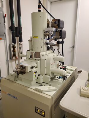
The JEOL 7500F Scanning Electron Microscope provides ultrahigh resolution of 0.8 nm at 30 kV and 1 nm at 1 kV. This SEM operates in high vacuum and is best suited for conductive specimens, but its low voltage resolution enables some nonconductive imaging. The 7500F is in the NCF Annex, located in Bay 6 of the Quattrone Nanofabrication Facility. Access to the cleanroom is required for access to the microscope. This microscope is especially useful for mid-process characterization in the cleanroom.
Training
Request training through NEMO. New users will complete at least two (2) training sessions with staff and demonstrate safe and competent operation of the tool to receive independent access (Prime time only: 9-5 weekdays.)
- Staff may require (or users may request) additional training before access is granted, or after initial training.
- Additional training for advanced techniques available upon request.
- 24/7 access may be granted at staff's discretion after completing at least 4 hours of independent use on the tool without incident.
- Staff may require refresher trainings after a period of disuse or after incidents.
User Responsibilities
General Expectations
- Reserve the tool through NEMO, then log in when you start and log out when finished. This enables the control PC monitor.
- Report problems through NEMO.
Specimen Handling
- Do not load specimens taller than the top of the sample holder. If a sample is lost in the chamber due to improper loading, tool access may be restricted.
- Do not overtighten set screws or remove them, unless necessary.
- Do not bring carbon tape into the cleanroom.
Data Management
- Images are stored on the EDAX computer. This is connected to the internet. Transfer images online or plug a USB drive into the Data PC on the right side of the console table.
- Images are periodically deleted when the drive has too little free space.
- Respect other users if they are operating the SEM when you come to retrieve your images.
Detectors
Secondary and backscattered electron detectors allow for imaging of sample surfaces, whereas a scanning-transmission electron detector shows the internal structure of materials. Through a stage biasing system, referred to as “gentle-beam” mode, the electron beam interacting with the sample may be reduced to a fraction of the accelerating voltage of the gun, allowing for the imaging of soft or insulating samples without the need for carbon or metal coating. An EDAX Energy Dispersive x-ray spectrometer (EDS) is available for chemical characterization via spectra or element maps.
Sample Holders
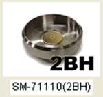
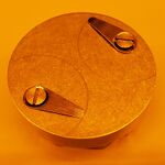
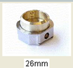
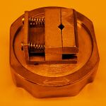
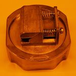
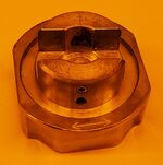
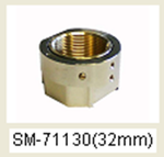
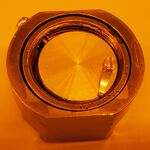
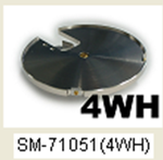
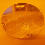
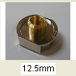
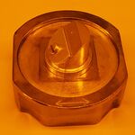
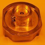
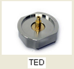
Compatible sample holders are required when loading specimens into the 7500F, and the appropriate holder must be selected after loading the specimen onto the stage.
Please note that the 2BH, 26mm, 4WH, and 12.5mm holders are modular. If the holder you need is not mounted in a base with the dovetail groove on the bottom, loosen the set screw with the provided allen key, remove the unneeded holder, replace the required one, and gently tighten the set screw.
| Select | For Holder |
|---|---|
 |
|
 |
|
 |
|
 |
|
 |
|
 |
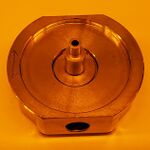 Available upon request Available upon request
|
Troubleshooting Tips
See the SEM Troubleshooting section for more detailed information.
To improve image quality, you may need to change one or multiple settings.
| Setting | Range | Notes |
|---|---|---|
| Scan Speed | 1-12 (arbitrary) | Assignable to 4 presets (quick 1,2 and fine 1,2) Slow speeds (higher numbers) yield less noisy images, but may introduce more charging. Change in Setup > Operation Settings. |
| Detector | SEI or LEI (lower) | Both are electron detectors. SEI is positioned directly above the specimen and yields fewer shadows, more material contrast. Best for very flat specimens. SEI detects a combination of secondary and backscattered electrons which can be tuned with the r-filter. LEI is positioned lower in the chamber and offset from the beamline. LEI displays more shadows, may reduce the appearance of charging, and is better for long working distances (greater than 8mm.) LEI detects only secondary electrons. Other detectors are available for dedicated backscattered electron imaging and transmitted electron imaging. Contact staff for more information. |
| Voltage* | 0.5kV-30kV 0.1kV-3kV in gentle beam mode |
Low voltages are better for imaging surface detail and preventing specimen damage or charging in semi- to non-conductive specimens. High voltages may yield better resolution, better material contrast, and are better for longer working distances and analytical techniques such as EDS. |
| Probe Current* | 1-14 (arbitrary) | Recommended imaging range: 7-10. Smaller number yields smaller probe/spot size and lower specimen current: resulting in noisier images but higher theoretical resolution. Recommended EDS range: 11-14. Larger number yields larger probe/spot size and higher current: suitable for low magnification imaging and characterization techniques such as EDS or backscattered imaging. Resolution reduced at high magnifications. |
| Depth of Field* | Focus Depth-Resolution, 4 stops | This slider changes the depth of field by modifying the interaction angle. Positioning slider at Resolution yields highest resolution for flat surfaces, but is not suitable for highly topographic specimens. |
| Emission Current* | Maximum: 20uA | Recommended imaging at highest available current. Reduced emission current yields noisy image, but may reduce charging on minimally conductive specimens. |
| Imaging Mode | LM (low magnification) SEM (high magnification) GB-H (gentle beam, high) GB-L (gentle beam, low) |
Low magnification mode suitable for navigating, imaging below 10kX. SEM mode suitable for most samples Gentle beam modes apply voltage bias to the stage to reduce landing energy without sacrificing resolution. Ask staff for assistance before using gentle beam modes. |
* Changing these settings will require some realignment of the beam
EDS with APEX
APEX by EDAX is installed on the companion computer for EDS data collection and analysis. A guide for this program is available on our reference website.