Difference between revisions of "ABM3000HR Mask Aligner"
(update tool owner, update to NEMO) |
(update location to Bay 6) |
||
| Line 8: | Line 8: | ||
| Instrument_Type = Lithography | | Instrument_Type = Lithography | ||
| Staff_Manager = [[Ana Cohen | Ana Cohen]] | | Staff_Manager = [[Ana Cohen | Ana Cohen]] | ||
| − | | Lab_Location = | + | | Lab_Location = Bay 6 |
| Tool_Manufacturer = ABM | | Tool_Manufacturer = ABM | ||
| Tool_Model = 3000HR | | Tool_Model = 3000HR | ||
| NEMO_Designation = MA-03 | | NEMO_Designation = MA-03 | ||
| − | | Lab_Phone = | + | | Lab_Phone = xxxxx |
| SOP Link = [https://repository.upenn.edu/scn_sop/10/ SOP] | | SOP Link = [https://repository.upenn.edu/scn_sop/10/ SOP] | ||
}} | }} | ||
Revision as of 16:26, 12 March 2024
 |
|
| Tool Name | ABM 3000HR Mask Aligner |
|---|---|
| Instrument Type | Lithography |
| Staff Manager | Ana Cohen |
| Lab Location | Bay 6 |
| Tool Manufacturer | ABM |
| Tool Model | 3000HR |
| NEMO Designation | MA-03 |
| Lab Phone | xxxxx |
| SOP Link | SOP |
Description
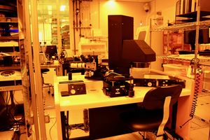
The ABM Mask Aligner is a manual and versatile mask aligner with top-side alignment and substrate capabilities from 100mm down to small pieces. Requires a 5" mask or 5" glass plate with film mask.
Applications
Tool is used primarily for SU8 exposure. It can also be used for aligning PDMS components for PDMS-to-PDMS bonding.
Exposure time = dose (mJ/cm^2) / intensity (mW/cm^2) Dose can be determined from the resist data sheet. See table below for intensities.
To obtain vertical sidewalls with a Cr glass mask, use the long pass filter (PL-360-LP) which eliminates UV emission below 350nm. Do not use with film masks. Inherent defects in film masks will be accentuated, resulting in worse results.
| NO MASK | 20 mW/cm^2 |
| GLASS MASK | 17.5 mW/cm^2 |
| GLASS + FILM MASK | 13.7 mW/cm^2 |
| GLASS + LP FILTER | 9.4 mW/cm^2 |
| GLASS + FILM + LP FILTER | 7.4 mW/cm^2 |
Calibration
MA-03 Mask Aligner Calibration SOP TJV 8/23/22
- Initial front panel settings:
- POWER switch: off
- INTENSITY Meter: WATTS
- CURRENT/VOLTS: VOLTS
- C/P Mode
- All 5 knobs turned counterclockwise
- Shutter closed
- Turn on Power switch
- Depress Start button and hold it in to start the lamp. (Be patient)
- Give 5 minutes for the power meter to read the proper wattage
- Use knob below mode to adjust wattage to desired setting (300ish)
- Open Shutter and measure intensity using external powermeter
- Set intensity/power switch to intensity
- Adjust calibration knob until intensity/power meter reading equals the intensity measured on external device (be patient, let it have some time before adjusting). Lock CAL knob
- Set Mode to C/I
- Adjust set knob to desired intensity and Lock knob.
NOTE: - Our set knob seems to have a decaying sensor. Sometimes, it cannot be used to adjust intensity. In this case:
- Follow steps (1)- (6)
- Continue in C/P mode and use the knob under mode to adjust the intensity to desired value.
- 350watts should give 20 on the power meter in Channel A. If it requires more than that, we most likely need a new bulb. 350 watts is at the top range of capability.
Resources
SOPs & Troubleshooting
- SOP: SOP
- Video for basic tool use (no audio, 5.52min):Basic Video
- Video (LayoutEditor - negative resist alignment marks): Video
- The potentiometer for the inspection microscope light source on the MA-03 is a bit touchy, so only adjust the intensity if needed. If you find that adjustments make the light turn off, press down lightly as you rotate back and forth until you get it working again.